Encoders
Encoders
An Encoder is a combinational circuit that performs the reverse operation of Decoder.
It has maximum of 2n input lines and ‘n’ output lines.
It will produce a binary code equivalent to the input, which is active High
The encoder encodes 2n input lines with ‘n’ bits. It is optional to represent the enable signal in encoders.
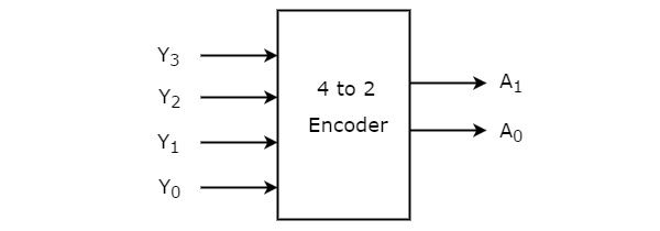
4 to 2 Encoder
It has 4 inputs and 2 outputs
Truth Table
This is the truth table of 4 to 2 Encoder
A1 = Y3 + Y2
0

when case Y1 is one and Y3 is one , A0 is one. Therefore we can say,
A0 = Y3 + Y1
Circuit
Encoders are designed with logic gate such as an OR-gate
How to draw 4 to 2 Encoder and simulate
click on the arrow icon
create circuit with two OR Gates
Set Wires
put inputs and outputs
click on the Simulate icon
Simulate Circuit
Octal to Binary Encoder
Octal to binary Encoder has eight inputs, Y7 to Y0 and three outputs A2, A1 & A0

Truth Table of Octal to Binary Encoder
At any time, only one of these eight inputs can be ‘1’ in order to get the respective binary code
Explanation
Circuit
How to create and Simulate
click on the arrow icon
create circuit with two OR Gates
Set Wires
put inputs and outputs
click on the Simulate icon
Simulate Circuit
This is to opposite in 3 - 8 Decoder
It accepts eight inputs and produces 3 bit output codes.
Priority Encoder
Four inputs, Y3, Y2, Y1, and Y0, and two outputs, A1 and A0, make up a 4 to 2 priority encoder. The input Y3 is given the highest priority, whereas the input Y0 is given the lowest. Even if more than one input is ‘1' at the same time in this situation, the output will be the binary code corresponding to the input with greater priority.
We looked at another output, V, to see if the code at the outputs was correct.
- The code available at the outputs is valid if at least one of the encoder's inputs is "1." V will equal 1 in this situation
- If all of the encoder's inputs are zero, the code that appears on the outputs is invalid. V will be equal to 0 in this situation.
Truth Table of 4 to 2 Priority Encoder
The simplified Boolean functions are
Similarly, we will get the Boolean function of output, V as
3
0


How to create Circuit and Simulate
Circuit diagram contains two 2-input OR gates, one 4-input OR gate, one 2input AND gate & an inverter.
Even though many inputs are equivalent to ‘1' at the same time, an AND gate and inverter combination is employed to provide a valid code at the outputs. As a result, based on the priority assigned to each input, this circuit encodes the four inputs with two bits.


Comments
Post a Comment